General Parameters
General Parameters calculations allow you to calculate the characteristic impedance and a number of secondary transmission line parameters, determine the loss level in transmission lines, and calculate the transmission line length for a given loss level.
Example
General Parameters Calculation Walkthrough
To perform a General Parameters calculation with frequency-dependent analysis, follow these steps:
-
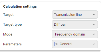
Set the initial calculation settings:
- Set Target to
Transmission line - Set Target type to
Single-ended,Diff pair,Coplanar single-ended, orCoplanar diff pair - Set Mode to
Frequency domain - Set Parameters to
General
- Set Target to
-
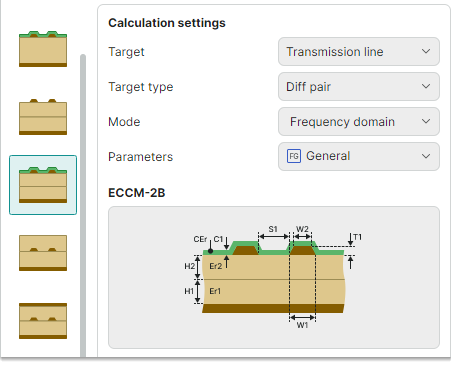
Select the required transmission line model and review it in the preview area.
-
Define the input parameters for the transmission line.
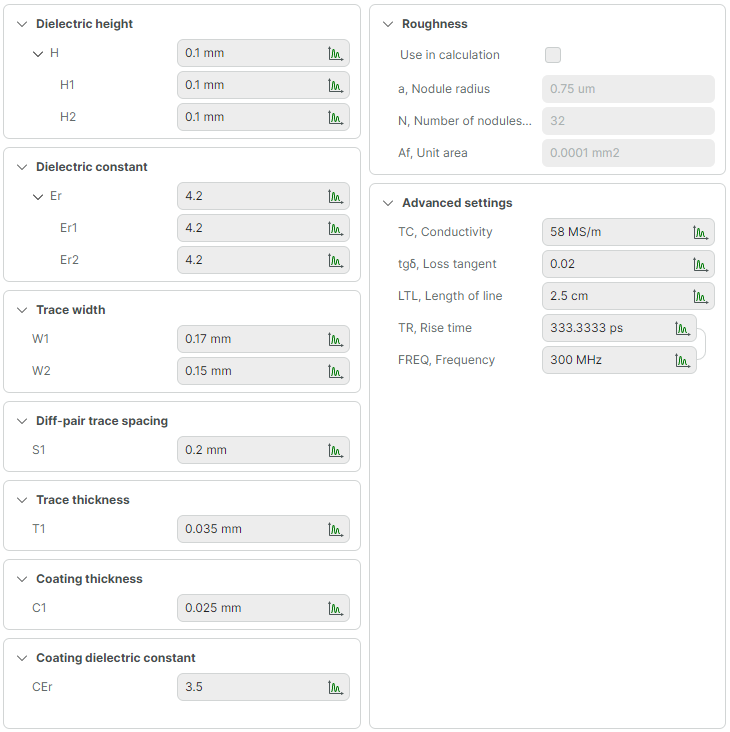
Available parameters are listed below. Some of them may not be available for certain transmission line types.
- H – Dielectric thickness (mm). For each dielectric layer, you can specify its own thickness using the H1..H4 parameters (the number of H(n) parameters is determined by the number of dielectric layers).
- Er – Dielectric constant. For each dielectric layer, you can specify its own dielectric constant using the Er1..Er4 parameters (the number of Er(n) parameters is determined by the number of dielectric layers).
- W1 – Trace width (mm).
- W2 – Trace width after undercut (mm).
- T1 – Trace thickness (mm).
- C1 – Coating thickness (mm).
- CEr – Coating dielectric constant.
- D1 – Distance from the trace to the reference plane (mm).
- S1 – Diff-pair trace spacing (mm).
- TC – Conductor conductivity (S/m).
- tgδ – Loss tangent.
- LTL – Line length (mm).
- TR – Rise time (ps).
- FREQ – Frequency (MHz).
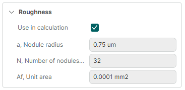
To account for surface roughness in the calculation, enable the Use in calculation checkbox in the Roughness section. The roughness parameters include:
- a – Nodule radius (µm).
- N – Number of nodules in a unit area.
- Af – Unit area (mm²).
-
Click Calculate in the lower-right corner of the calculation tab to run the calculation.

Before running the calculation, you can click the dropdown arrow next to the Calculate button to choose between two calculation saving options:
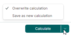
- Overwrite calculation – Saves the modified input parameters to the current calculation, overwriting previous data.
- Save as new calculation – Saves the modified input parameters to a new calculation. This calculation will appear in the Projects panel.
Calculation Results for Single-Ended and Coplanar Single-Ended Lines
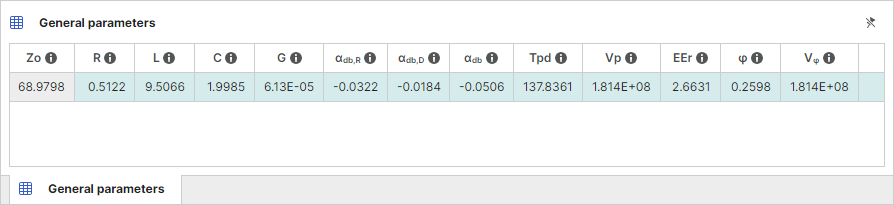
For single-ended and coplanar single-ended transmission lines, the following parameters are calculated:
- Zo – Characteristic impedance (Ohm).
- R – Resistance (Ohm).
- L – Inductance (nH).
- C – Capacitance (pF).
- G – Dielectric conductance (S).
- αdb,R – Conductor attenuation (dB).
- αdb,D – Dielectric attenuation (dB).
- αdb – Total attenuation (dB).
- Tpd – Propagation delay (ps).
- Vp – Signal propagation velocity (m/s).
- EEr – Effective dielectric constant.
- ɸ – Phase (rad).
- Vɸ – Phase velocity (m/s).
Calculation Results for Differential and Coplanar Differential Lines
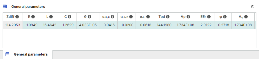
For differential and coplanar differential transmission lines, parameters are calculated in several display modes at the same time:
- Differential – The differential characteristic impedance (Zdiff).
- Common – The characteristic impedance in common mode (Zcomm).
- Odd – The characteristic impedance in odd mode (Zodd).
- Even – The characteristic impedance in even mode (Zeven).
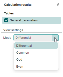
The results table displays calculated transmission line parameters for one mode, which is selected in the Calculation results panel.
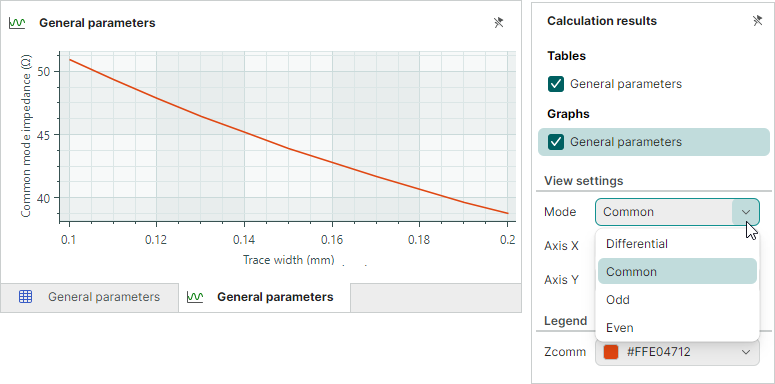
Use the View settings → Mode drop-down in the Calculation results panel to select the required result display mode:
Parametric Sweep
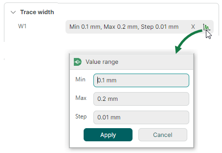
Parametric sweeps for frequency-dependent General Parameters calculations are performed similarly to sweeps in Lossless mode: you need to specify a range of values and a step for one of the input parameters.
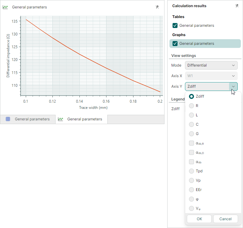
In the results graph, the Y-axis can display any of the calculated parameters (Zo, R, L, C, G, αdb,R, αdb,D, αdb, Tpd, Vp, EEr, ɸ, Vɸ). To specify the parameter to display, select the Graphs → General parameters checkbox in the Calculation results panel, and then use the Axis Y drop-down.
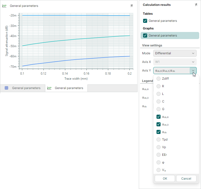
The calculated attenuation parameters (αdb,R, αdb,D, αdb) can be displayed simultaneously in the graph. To do this, select any combination of these parameters in the Axis Y drop-down.
For differential and coplanar differential lines, the graph can display transmission line parameters calculated for Differential, Common, Odd, and Even mode. You can select the required mode in the View settings → Mode drop-down in the Calculation results panel.
See Also