Calculate S-Parameters in the Time Domain
In this tutorial, we'll calculate S-parameters in the time domain for a matched stripline transmission line. This line is located on the third layer of a sample 6-layer PCB stackup shown below. The board thickness is 1.5 mm.
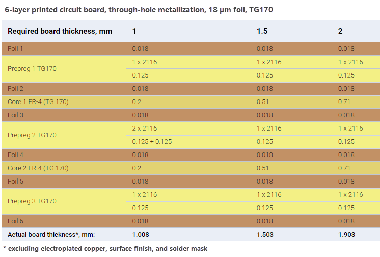
Using time-domain analysis, you can reconstruct the signal waveform using the convolution mathematical function. For transmission lines, the S11 and S21 coefficients are typically most important.
-
First, determine the trace width required to achieve a characteristic impedance of
50 Ohmfor anOffset stripline (OS-1B1A)structure, as demonstrated in the Calculate Trace Width tutorial.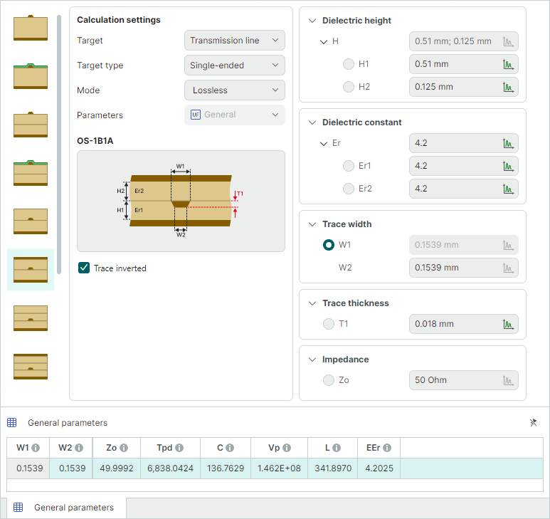
The calculated trace width is
0.1539 mm. -
In the Calculation settings panel, switch calculation mode to
Time domainand set the Parameters option toS-parameters. The previously entered transmission line parameters will retain their values.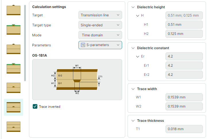
-
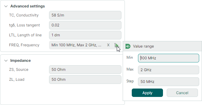
Set the following calculation parameters:
- Set LTL, Length of line to
100 mm - Set ZS, Source impedance to
50 Ohm - Set ZL, Load impedance to
50 Ohm - Set FREQ, Frequency to a range from
100 MHzto2 GHzwith a step of50 MHz
- Set LTL, Length of line to
-
Run the calculation.
-
In the Calculation results panel, select the S-parameters graph. Then set the View → S-parameter option to
S11.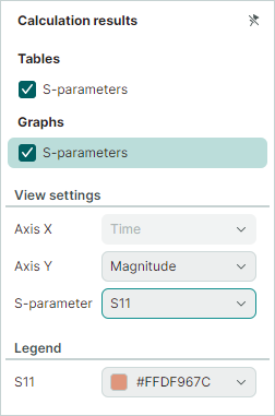
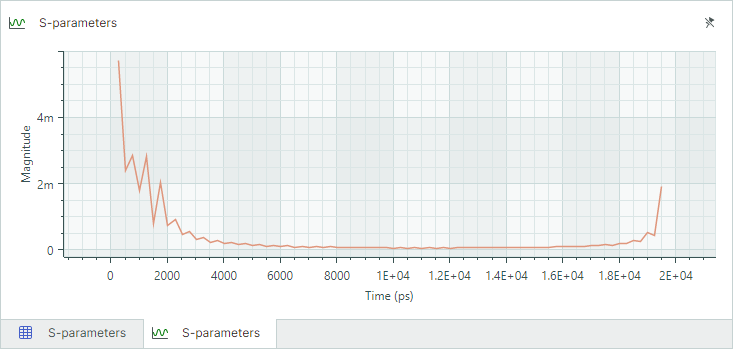
The graph at the bottom will display the S11 parameter (the reflected signal) as a function of time.
Calculations for differential transmission lines can be performed in the same way.