Calculate Crosstalk
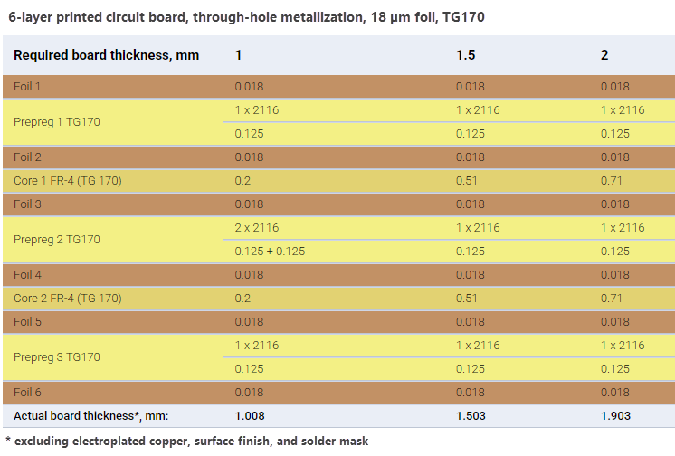
In this tutorial, we'll calculate crosstalk for a matched microstrip transmission line with a solder mask. This line is part of a DDR4 module operating at 2400 MHz and is located on the first layer of a sample 6-layer PCB stackup shown below. The board thickness is 1.5 mm. The target characteristic impedance is 40 Ohm.
Note
In SimPCB Lite, crosstalk is calculated for matched transmission lines, meaning that the source and load impedances are equal to the characteristic impedance of the line.
-
First, determine the trace width required to achieve a characteristic impedance of
40 Ohmfor aCoated microstrip (CM-1B)structure, as demonstrated in the Calculate Trace Width tutorial.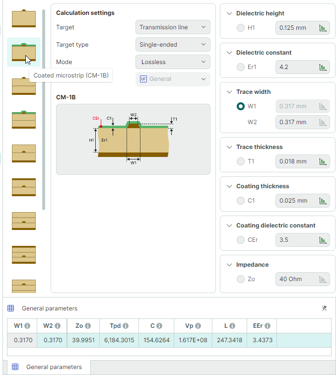
The calculated trace width is
0.3170 mm. -
In the Calculation settings panel, switch calculation mode to
Frequency domainand set the Parameters option toCrosstalk. The previously entered transmission line parameters will retain their values.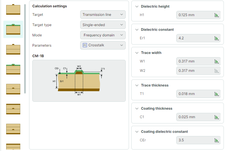
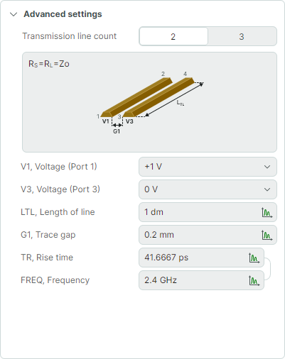
In the Advanced settings panel, set the following parameters:
- Set V1, Voltage (Port 1) to
+1 V - Set V3, Voltage (Port 3) to
0 V - Set LTL, Length of line to
100 mm - Set G1, Trace gap to
0.2 mm - Set FREQ, Frequency to
2400 MHz
- Set V1, Voltage (Port 1) to
-
Run the calculation. The results will be displayed in a table at the bottom of the window.
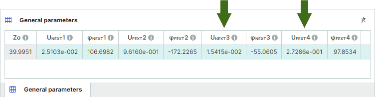
- Near-end crosstalk (UNEXT3) is
0.015 V - Far-end crosstalk (UFEXT4) is
0.27 V
Note that the calculation is performed at a fixed voltage on Port 1, which can be configured to
+1 Vor-1 V. The actual crosstalk level scales proportionally with the voltage applied to Port 1.For example, if the input signal on Port 1 is
5 V, the resulting crosstalk values are:- Near-end crosstalk (UNEXT3):
5 × 0.015 = 0.075 V - Far-end crosstalk (UFEXT4):
5 × 0.27 = 1.35 V
- Near-end crosstalk (UNEXT3) is