Calculate Transmission Line Length for a Specific Signal Loss Level
In this tutorial, we'll calculate the length of a high-speed microstrip transmission line with a solder mask for a DDR5-4800 module operating at 4800 MHz. This line is located on the first layer of a sample 6-layer PCB stackup shown below. The board thickness is 1.5 mm, and the allowable loss per line is approximately -3 dB. The target characteristic impedance of the transmission line is 40 Ohm.
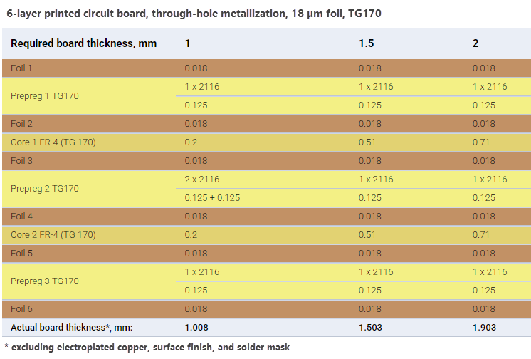
This tutorial employs the frequency analysis to determine the maximum transmission line length when the allowable loss level is known.
Tip
The typical use of the frequency analysis is to determine transmission line losses, the characteristic impedance at a specific frequency, and a set of secondary transmission line parameters (RLGC, which can be used to build ABCD matrices).
Important! Transmission line losses in frequency analysis calculations are computed for a matched line.
-
First, determine the trace width required to achieve a characteristic impedance of
40 Ohmfor aCoated microstrip (CM-1B)structure, as demonstrated in the Calculate Trace Width tutorial.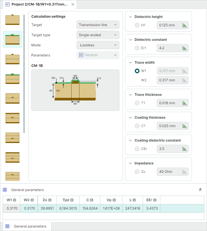
The calculated trace width that corresponds to an impedance value of
40 Ohmis0.3170 mm. -
Switch calculation mode to
Frequency domainin the Calculation settings panel. The previously entered transmission line parameters will retain their values.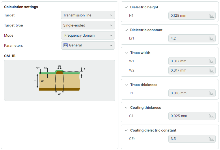
In the Advanced settings panel, set the following parameters: - Set LTL, Length of line to a range from
10 mmto300 mmwith a step of10 mm- Set FREQ, Frequency to4800 MHz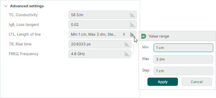
-
Run the calculation.
-
In the Calculation results panel, do the following:
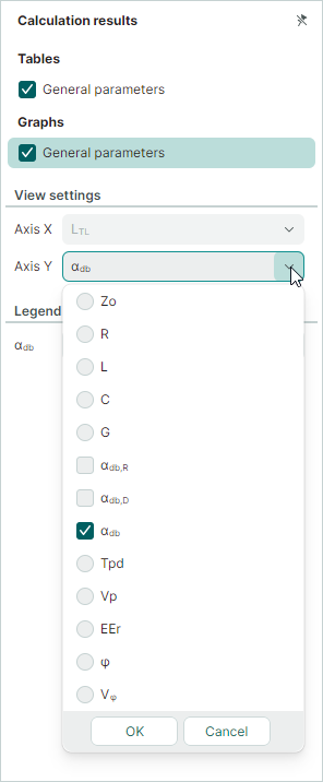
- Enable the Graphs → General parameters checkbox. This will display a chart showing the results.
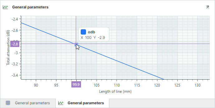
- Set the Axis Y parameter to αdb to show the total attenuation along the Y axis.
See the calculation results shown in the table and graph at the bottom of the window to determine the transmission line length for a loss level of
-3 dB.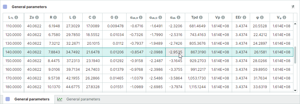
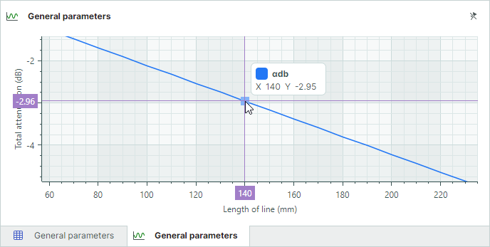
The transmission line length at a loss level of
-3 dBis approximately140 mm. -
To take into account the surface roughness, enable the Roughness → Use in calculation checkbox and run the calculation again.

Now, the transmission line length at a loss level of
-3 dBis approximately100 mm.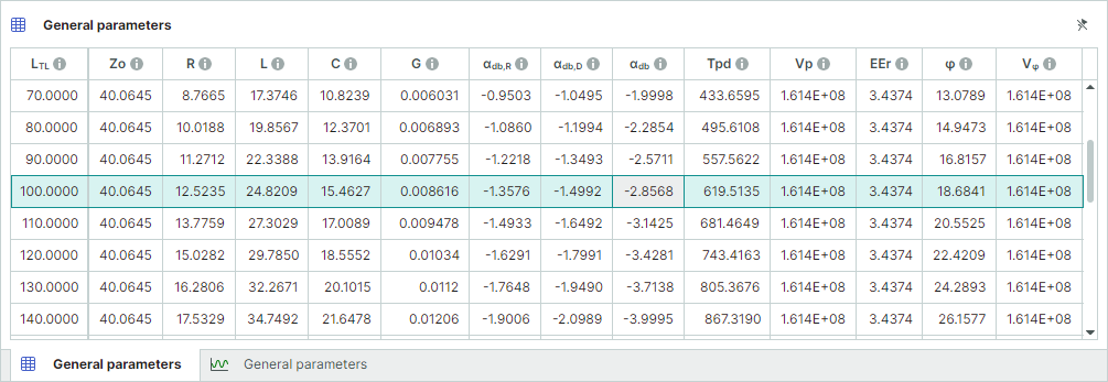
Note that a number of additional transmission line parameters were also computed along with the TL length.