Calculate Trace Gap
In this tutorial, we'll determine the required spacing between transmission lines to maintain an acceptable crosstalk level. This is a continuation of the Calculate Crosstalk tutorial, which evaluates crosstalk for a transmission line operating at 2400 MHz.
The target trace gap must limit crosstalk to 10% of the 1 V input signal (no more than 100 mV).
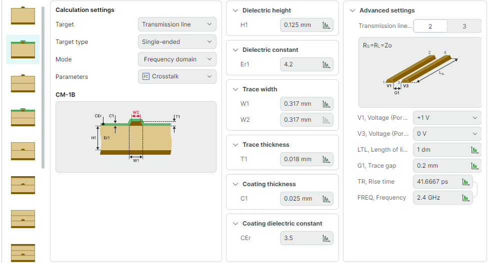
The transmission line has the following input parameters:
- Set W1, Trace width (Zo =
40 Ohm):0.3170 mm - Set LTL, Length of line:
100 mm - Set V1, Voltage (Port 1):
+1 V - Set V3, Voltage (Port 3):
0 V - Set FREQ, Frequency:
2400 MHz
-
Set the G1, Trace gap parameter to a range from
0.1 mmto1 mmwith a step of0.05 mm.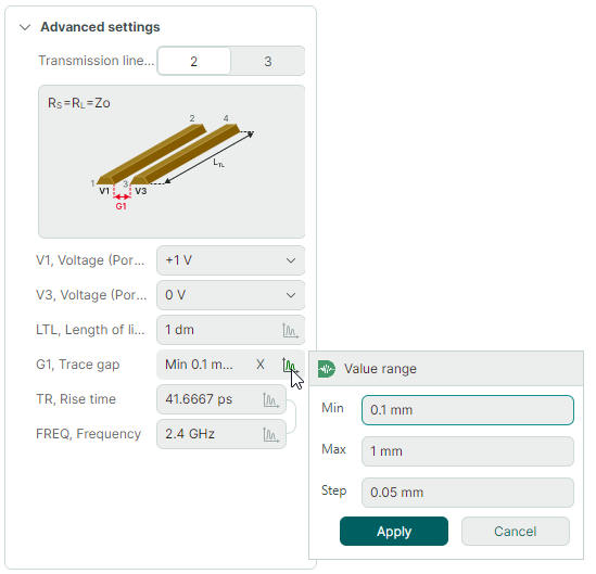
-
Run the calculation.
-
In the Calculation results panel, select
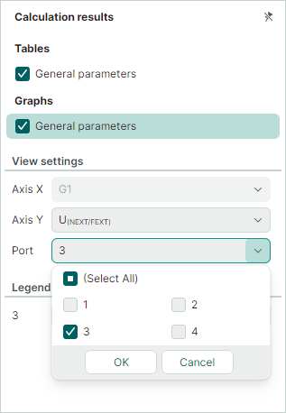
Graphs → General parameters. Set the following options to display the near-end crosstalk level (U(NEXT/FEXT)on Port 3) in the graph:- Set Axis Y to
U(NEXT/FEXT) - Set Port to
3
The calculation results are displayed in both table and graph formats at the bottom of the window:
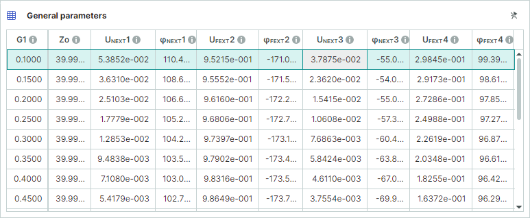
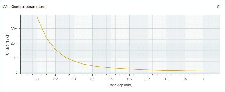
The results confirm that the crosstalk level (UNEXT3 =
37.8 mV) at the minimum trace gap (G1) of0.1 mmdoes not exceed the maximum allowable value (100 mV). - Set Axis Y to
-
In the Calculation results panel, select
Graphs → General parameters. Set the following options to display the far-end crosstalk level (U(NEXT/FEXT)on Port 4) in the graph:- Set Axis Y to
U(NEXT/FEXT) - Set Port to
4
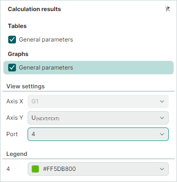
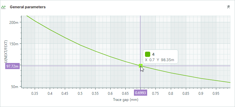
The results graph and table show that at the far end of the line, the trace gap (G1) must be at least
0.7 mmto keep crosstalk below the acceptable100 mVthreshold (UFEXT4 =98.35 mV).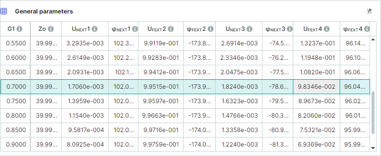
- Set Axis Y to