Model
A model is a specific transmission line or via structure for which to perform a calculation. See the following articles for information on supported transmission line and via models:
A model is automatically created in the Projects panel when you create a calculation. By default, the model is assigned the code name (short name) of the selected transmission line or via structure.
Transmission Line Model Code Names
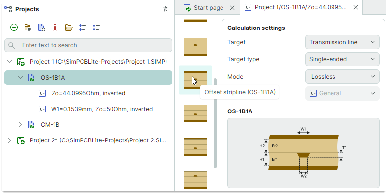
The code name of a transmission line model consists of an abbreviation of the transmission line type and the number of dielectric layers above ('A') and below ('B') the conductor.
For example, the name OS-1B1A is used to represent the "Offset stripline" structure with dielectric layers above ('A') and below ('B') the conductor.
Via Model Code Names
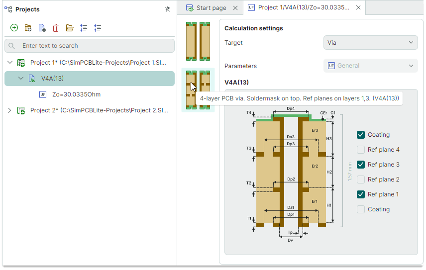
A via model code name starts with 'V' (via) followed by the number of layers in the board stackup. It then specifies the mask coating positions: 'A' (above) and/or 'B' (below). The positions of reference layers are indicated in parentheses.
For example, the code name V4A(13) is used for a via model in a four-layer PCB with mask on the top layer and reference planes on layers 1 and 3.
Add New Calculations
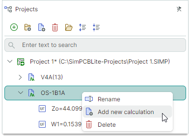
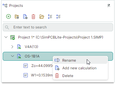
Right-click the model in the Projects panel and click Add new calculation to create a new calculation for the selected model.
Delete Model
-
Right-click the model in the Projects panel and select Delete.
or
-
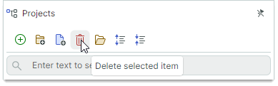
Click the Delete selected item button in the Projects panel toolbar.
Rename Model
To rename the model, you can do one of the following:
- Select the model (for instance, by a mouse click) in the Projects panel, and then press F2, or click the model name again.
or
-
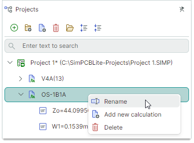
Right-click the model, and select Rename from the context menu.
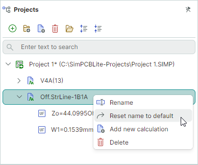
If you need to restore the default name after renaming a model, use the Reset name to default command from the context menu.
See Also