Calculate Differential Impedance
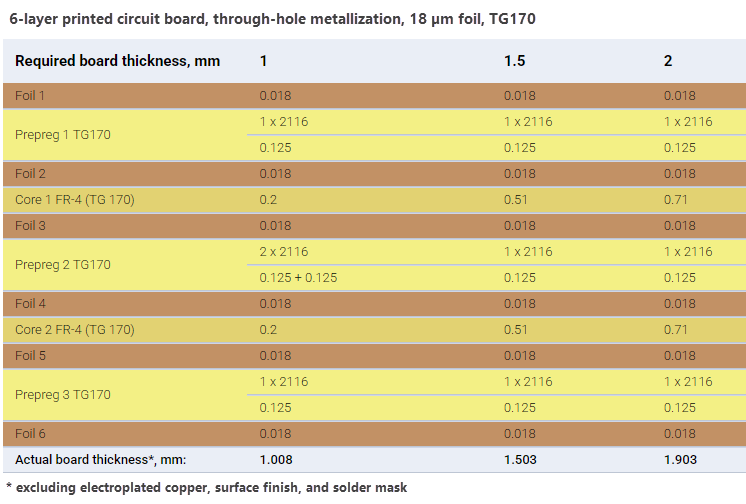
In this tutorial, we'll calculate the differential impedance and secondary parameters of a differential stripline transmission line. This line is located on the third layer of a sample 6-layer PCB stackup shown below. The required PCB thickness is 1.5 mm.
-
In the Calculation settings groupbox:
- Set Target to
Transmission line - Set Target type to
Diff pair
Then select the
Edge-coupled offset stripline (ECOS-1B1A)structure.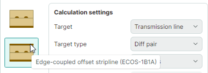
- Set Target to
-
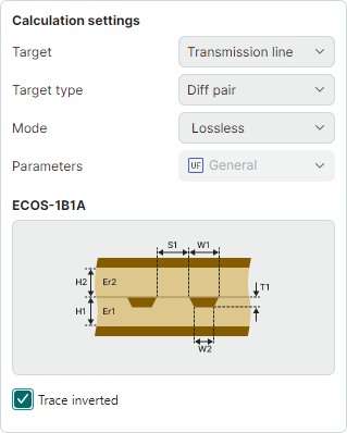
Define the initial calculation settings:
- Set calculation mode to
Lossless - Enable the Trace inverted checkbox.
- Set calculation mode to
-
Enter the known geometric and electrophysical parameters of the transmission line in accordance with the target PCB stackup:
-
Set H1, Dielectric height below to
0.51 mm - Set H2, Dielectric height above to
0.125 mm - Set T1, Trace thickness to
0.018 mm - Set W1, Trace width and W2, Upper trace width to
0.2 mm -
Set S1, Diff-pair trace spacing to
0.2 mm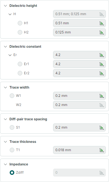
-
Click Calculate to run the calculation.
The calculation results will be displayed in a table at the bottom of the window.
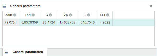
The calculated differential impedance (Zdiff) is
79.0754 Ohm.